Our Mic Cupboard
- MICROPHONE PREAMPS
- MICROPHONES - DYNAMIC
- MICROPHONES - FET
- MICROPHONES - THE PRODUCER'S CHOICE
- MICROPHONES - TUBE
- MODS
- PARTS
- SHOCK MOUNTS
Subscribe
European Clients
www.advancedaudio-europe.com Advanced Audio Microphones Europe take care of ALL European sales and warranty. info@advancedaudio-europe.comShipping
Due to the boutique nature of our microphones, each one spends some time on the bench. We strive to ship within 72 hours of an order being placed.Questions? info@advancedaudio.caNews » multi-pattern
The U87 LDC multi-pattern condenser Microphone Posted on November 02, 2019
If you have reached this page then you are most likely looking for information on the U87 recording and broadcast Microphone:
The U87 is one the most recognizable and widely used condenser Microphones in modern broadcast and recording studio history.
Why was the U87 Microphone a favourite for voice recording and radio/tv personalities as well as a recording studio spot mic?:
The U87 features a large dual sided (double diaphragm) condenser capsule. This double sided capsule in conjunction with a 3-pattern switch on the front of the microphone allowed for the microphone’s variable polar pickup patterns to be easily switched from omni-directional, to cardioid and through to figure 8.
The Cardioid pattern is preferred for voice work because it rejects sound from both the rear and each side of the microphone. The U87 provided a present but warm sound for voice work.
In the recording studio OMNI and Figure 8 polar patterns are very useful features as well being able to roll out the low frequencies plus reduce the sensitivity of the mic when its used in close proximity to capture loud sound sources.
Rear of U87 showing the Low Cut/HP filter and the -10db attenuation switches.
On the rear of the U87 are two switches; one switch provides the -10 dB of attenuation enabling the microphone to handle sound pressure levels up to 1o dB louder before the on-set of mic distortion. The 2nd switch will reduce the low-frequency response below 150hz to compensate for an increase in low frequencies know as proximity effect. This effect becomes more prominent as the source get closer than 30cm from the microphone in Cardiod or Fig 8 patterns. This high pass filter also known as a rumble filter or low cut will reduce “P’s” popping or low frequency rumble picked up by the very sensitive condenser capsule of the U87.
An advantage of the OMNI directional polar pattern in modern recording?:
Note, when a microphone is placed in OMNI there will be no proximity effect present. In a quiet and well treated studio room OMNI can be quite effective in reducing acoustic guitar boom.
Where can the U87 be used?:
The U87 is often chosen for general purpose recording applications in professional recording studios, radio stations, television stations and film sound stages. The U87 can be used as a main microphone for orchestral recordings or as a spot microphone for single instruments. Today it is primarily used as a vocal microphone for many different types of music vocal and speech recording applications as well as for radio announcers.
The U87 is known as a front address microphone. In cardiod the microphone will only pickup from the front where the polar pattern switch is located. In Figure 8 it will pickup from the front and rear but sound reaching the left and right sides of the microphone will be rejected. In OMNI the U87 will pickup 360 degrees around the front and rear. By engaging the HP (low cut) filter, low frequency audio interference or “masking” through subsonic and low frequencies sources are effectively reduced.
How many versions of the U87 are there and what are the differences between these two?:
U87i vs U87Ai
There are two basic versions of the U87. The early version was designated the U87i microphone which was built from 1967 to 1986. This version was designed to work from internal batteries as well as “phantom power”. Phantom Power is remotely sent to the microphone through the microphone cable from 48 volts dc emanating at a mixer, microphone preamplifier or recording console. Phantom power came into common use in recording and broadcast studios during the early 70’s and by the 80’s most location mixers had also become “phantom power” capable.
The later U87Ai was made from 1986 to the present day. In the U87Ai the battery compartment was removed and the newer U87Ai can only be powered from a phantom power supply which connects 48v dc through the mic cable to the electronics without negatively effecting the audio quality of the microphone.
However, in the U87Ai the capsule’s working voltage was increased by a factor of 1/3 which increased the output coming from the mic’s capsule compared to the earlier U87i. This higher polarization voltage also increases the tension of the capsule’s diaphragm which creates a slight rise in the HF response of 2-3db.
This increase in the U87Ai’s capsule polarization voltage circuitry also reduces the operational headroom of the U87Ai compared to the U87i. This is due to the higher capsule sensitivity or output level from the higher polarization voltage placed on the capsule of the U87Ai. This yields a much higher sensitivity of 10 dB for identical sound pressure levels but there is a benefit as the signal-to-noise ratio is improved by 3 dB. The audio schematic or circuit diagram of the U87i vs the U87Ai are nearly identical except for how the K87 capsule is polarized.
You can review the information in the chart below and compare both the electrical specs of the U87i verses the U87Ai. This chart shows that the U87Ai has 5db less headroom. That is, the original U87i can handle a source level 5db louder before the on-set of distortion compared to the new U87Ai. Even, though the U87 is more often than not used for close miking audio sources, the U87Ai designers choose not to increase the headroom of the audio portion of the U87Ai circuit keeping the single FET class “A”circuit identical to the U87i.
The U87Ai has a nearly 3db better (unweighted) signal to noise but in this writers opinion the signal to noise is not as important as headroom when microphones are used in close proximity to a loud acoustical sources such as “rock” vocals, percussion or even dialogue associated with dramatic and animation voice recording.
Review the U87i specs compared to the U87Ai here?:
| Parameter | U87 | U87A(i) | rel. difference U87A/U87 |
| Sensitivity (cardioid) | -42 dBv | 31.1 dBv | 10.9 dB |
| weighted per CCIR 468-2) | 18 dBA | 12 dBA | -6 dB |
| unweighted | 25 dB | 23 dB | -2 dB |
| S/N (CCIR) | 76 dB | 82 dB | 6 dB |
| max. SPL (0.5% THD) | 122 dBspl | 117 dBspl | -5 dB |
| (with 10 dB pad) | 13 RE2 dBspl | 127 dBspl | -5dB |
| dyn. range of amplifier | 104 dB | 105 dB | 1 dB |
| max. output (<0.5% THD) | 200 mV | 390 mV | |
| -14 dBv | -8.2 dBv | 5.8 dB | |
| max. input (test port) | 320 mV | 390 mV | 1.7 dB |
| Transducer capsule | K87 | K870 (K67.87A) |
More on the audio electronics circuitry of the U87?:
The U87i and the U87ai both use the same K87 dual diaphragm capsule. Due to the laws of physics a condenser microphone’s capsule has a rising high frequency response. This means high frequency content which is roughly those frequencies above 3khz are emphasized more than lower frequencies and the result is that the mic’s amplifier has to work harder above 3khz. The U87i and U87Ai both incorporate a HF de-emphasis circuit to reduce this phenomenon which helps to retain the delicate headroom of the U87 audio circuitry. However, this de-emphasis circuit like any active equalizer circuit will cause slight phase anomalies to the audio signal.
Can an alternative microphone to the U87 be built for a more reasonable price and will it work for professional users?:
Does the Advanced Audio CM87 compare to the U87?:
The Advanced Audio CM87 is a microphone designed to provide the same features and sound signature as the venerable U87 but at a much lower price. The CM87 mic has a frequency response within 2db of a U87i or U87Ai across its audio bandwidth.
The CM87 vs the U87?:

The audio circuit of the CM87 increases the headroom of the mic’s electronics significantly.
This allows the CM87 microphone to handle louder sound sources than even the U87i while retaining the increased signal to noise ratio of the U87Ai. The CM87 can be purchased for nearly 1/10th the price of U87Ai. It offers an alternative to any U87 version at a much better price point.
How is this possible?:
This is possible because in the 21st century high quality electronic components are much cheaper and more accurate that those components made in the 1960’s. Also, the metalwork can be now manufactured with computer controlled milling machines dropping the manufacturing time significantly. The structure of the CM87 is also much more efficient and easy to assemble than the venerable U87. The price of the CM87 is also based on direct internet sales and there are no distributors or retail outlets taking a percentage of the profit. Plus any servicing goes directly back to the Advanced Audio shop and not back through a retailer or distributor which can significantly slow down service.
The CM87 like the U87 features a similar dual diaphragm, dual back-plate design which is polarized with the same voltage as the K87 capsule in the U87Ai. However, the AK67 capsule has a slightly larger surface allowing more damping holes to be computer drilled into the metal back-plate slightly reducing the high frequency increase of the capsules response compared to the K87 and providing a somewhat flatter response from the capsule.
How has the circuit of the CM87 been improved?:
The audio circuitry has also been improved by using a 2-stage circuit while still remaining class “A”. The CM87 has an emitter/follower class “A” discrete/fet circuit that utilizes the full 48v to energize the FET and the following silicon transistor increasing the headroom the audio circuit by 6db.
The other advantage of the emitter/follower circuit is that that output transformer can have a much lower turns ratio decreasing the loss in the transformer circuitry by 14db compared to the U87 circuit. This has the added advantage of reducing the signal to noise of the circuitry and increasing the headroom significantly.
The lower ratio transformer of the CM87 with its much lower loss allows a medium gain FET (field effect transistor) to be used and the overall headroom of the CM87 compared to the U87 is increased respectively. This allows the CM87 to even be used in front of a bass drum or inches above the hammers of a grand piano without any significant increase in harmonic distortion.
The CM87 also features a 3-pattern selector switch on the front of the microphone plus a -10db pad and HP filter on the rear of the microphone. These switches are high quality metal toggle switches that are more easily sourced than the custom made switches in the U87. The switches in the U87 are incredibly expensive and time consuming to fit and replace when they eventually become defective. Also, the head grill of the CM87 can be more easily removed than in the U87 without any chance of damaging the more delicate plastic switch levers used in the U87i and U87Ai.
Does the CM87 use de-emphasis in its circuit?:
The slightly larger AK67 with its smoother response and the extended headroom of the CM87 means that no de-emphasis is required in the circuit and the phase response is no longer compromised. The CM87 in field testing has been found to be on average slightly brighter sounding than an original U87i but not noticeably brighter than the later CM87ai. Like the U87 the CM87 has a very nice present an warm sound for voice work without being overtly sibilant.
Who uses Advanced Audio CM87 microphones?:
Sirius Satellite XM recently purchased 28pc CM87 microphones for all their on-air studios in Nashville. Plus the CM87 has quickly become one of the most used microphones in the ever expanding project studio market.
More specs and user information can be found on the Advanced Audio Web-site.
8 Comments
U47fet Microphone versus Affordable Alternative Posted on November 02, 2019
U47fet MICROPHONE VERSUS AFFORDABLE ALTERNATIVE
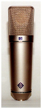
IF YOU HAVE FOUND THIS PAGE THEN YOU MOST LIKELY ARE LOOKING FOR HISTORY OF THE NEUMANN U47fet :
The U47 FET was developed and designed circa1969 as the source of tubes for the now famous and still popular U47 & U48 microphones started drying up.
During this time period, the “Cold War” and resulting “Space Race” had caused rapid advancement in electronic technology. During the late 60’s, now reliable and high quality silicon transistors were starting to be manufactured very economically compared to more costly tubes. Very “HiFi” and quiet audio circuits could now be manufactured with transistors instead of the older tube technology.
Considering this, along with the new trend of placing microphones very close to instruments and voices in Cardiod…Neumann decided to re–engineer the U47fet as a solid–state, single-pattern microphone, designed around a “state of the art” Field Effect transistor (FET) with 5 additional silicon transistors.
This new FET microphone circuit will now do the work of the tube in previous designs; matching the very high impedance capsule to the final low impedance balanced 150-200 ohm output of modern recording microphones.
The newly designed U47fet was in full production by early 1972 and it provided a welcome alternative the use of dynamic microphones for close recording of instruments that can deliver high SPL’s.
Although, the U47fet could be used easily to record an acoustic guitar, producers often preferred the brighter U47, U87 or AKG 414eb to the U47fet. However, It was lovely sounding on upright bass or in front of the guitar or bass amp.
FET CIRCUITS VERSUS TUBE CIRCUITS
A tube’s input and output impedances are much higher than we see in early transistor circuits. The output impedance at the transformer is typically 200 ohms.
However, with the development of the field effect transistor in the early 60’s; which has a much higher input impedance compared to early silicon transistors it was possible to built professional condenser broadcast and recording microphones with solid state devices. Modern field effect transistors could now offer better noise and gain figures than a single vacuum tube and were easier to power.
The typical FET “transconductance” or impedance to gain ratio is many times higher for a FET compared to a tube. This means that a FET can yield 94db more gain than an equivalent single tube circuit and provide a better signal to noise ratio than an equivalent tube circuit.
However, the tube is still used today for condenser microphone circuits because impedance matching is more important than obtaining maximum gain in typical condenser microphone circuits; plus tubes can take and incredible amount of “abuse” from excessive input levels or excessive power supply voltage variations compared to any solid-state device.
In a way the FET circuits are more detailed and with a slightly faster transient response than tube circuits while the TUBE circuits are more “forgiving” with a overload characteristic that is more “compressor” like than hard IC clipping.
Solid State circuits must be able to provide more “headroom” or maximum output before distortion compared to a tube amplifier to be preferred in listening tests.
Here is a reference to an AES Paper from 1973 comparing tube circuit to solid- state circuits in audio gear. This is a fascinating study and the full study is well worth reading for any enterprising recording engineer. All the findings are verified scientifically with double blindfold testing.
THE PAPER ASKED:
TUBES VS TRANSISTORS: IS THERE AN AUDIBLE DIFFERENCE?
Engineers and musicians have long debated the question of tube sound versus transistor sound. Previous attempts to measure this difference have always assumed linear operation of the test amplifier. This conventional method of frequency response, distortion, and noise measurement has shown that no significant difference exists. This paper, however, points out that amplifiers are often severely overloaded by signal transients (THD 30%). Under this condition there is a major difference in the harmonic distortion components of the amplified signal, with tubes, transistors, and operational amplifiers separating into distinct groups.
THE CONCLUSION OF THE STUDIO STATED:
“Vacuum-tube amplifiers differ from transistor and operational amplifiers because they can be operated in the overload region without adding objectionable distortion. The combination of the slow rising edge and the open harmonic structure of the overload characteristics form an almost ideal sound- recording compressor. Within the 15-20 dB "safe" overload range, the electrical output of the tube amplifier increases by only 2-4 dB, acting like a limiter. However, since the edge is increasing within this range, the subjective loudness remains uncompressed to the ear. This effect causes tube-amplified signals to have a high apparent level, which is not indicated on a volume indicator (VU meter). Tubes sound louder and have a better signal-to-noise ratio because of this extra subjective headroom that transistor amplifiers do not have. Tubes get punch from their naturally brassy overload characteristics. Since the loud signals can be recorded at higher levels, the softer signals are also louder, so they are not lost in tape hiss and they effectively give the tube sound greater clarity. The feeling of more bass response is directly related to the strong second and third harmonic components which reinforce the "natural" bass with "synthetic" bass [5]. In the context of a limited dynamic range system like the phonograph, recordings made with vacuum-tube preamplifiers will have more apparent level and a greater signal to system noise ratio than recordings made with transistors or operational amplifiers.”
THE TECHNICAL DETAILS OF THE U47
The U47 FET’s circuit was far more complex than any other Neumann fet microphones designed in this post tube era including the U87 and KM84.
The later U89 microphone featured a similar circuit to the U47fet but with a different capsule than either the K67 or K47.
However, in the U87 and the SDC, KM84 circuits a single FET impedance converter directly feeds an output transformer with a 10:1 ratio. But, in the U47 FET/U89 circuit the FET is buffered from the output transformer by 5 silicon transistors configured like a discrete OP amp to provide a class A/B output stage.
A sixth transistor serves as a voltage regulator to ensure the circuits working voltage and capsules polarization stays consistent at 43V allowing the 48v phantom supply a 10% working tolerance.
The U47fet circuit uses negative feedback to reduce the HF response of the K47 capsule much like a “HF limiter” giving the U47fet a tighter more controlled sound.
Although the FET model incorporated exactly the same K47 capsule as the original U47, the revised internal electronics, contributed to a darker sound signature in the Cardiod pattern compared either to the U47, M49 or the U87. Nevertheless, the U47 FET became a reliable “go to” workhorse microphone and it was highly regarded in high SPL settings whether in front of a kick drum, over the Timpani’s or in front of the bell on a French horn.
It was a favourite of mine in front of the kick, on trumpet, trombone, upright bass and the low end of a grand piano, or on a vocal where a U47 or C12 is a bit bright, or you have an overly sibilant singer and don’t want to resort to an even darker dynamic or ribbon microphone.
The U47fet was well regarded in its ability to handle extremely high sound-pressure levels. It can handle an SPL level of 147dB with the 10dB pad switched in. For, comparison a U47’s distortion will start to increase with levels above 120db. Although never as popular on vocals as the original U47…it sounds a little more “compressed” and has a slightly flatter response than the original 47 (which has a much broader 5dB presence boost) — the FET 47 was still quite usable in this role too, particularly for male vocals and speech. Its modest 2dB of presence boost between about 2 and 5 kHz is enough to aid clarity and intelligibility in a mix, while the gentle proximity boost adds a degree of body and warmth. (SOS July 2015).
Here is the schematic of the U47fet courtesy of RecordingHacks
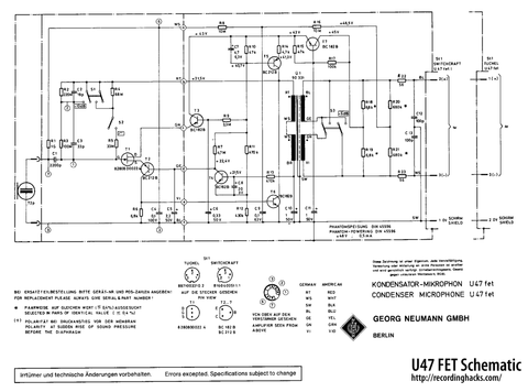
Note: the 5 transistors are all dc coupled. C10 protects the output transformer from passing DC and R13 is providing negative feedback to the transistor circuit.
T4 & T5 provide a class A/B NPN-PNP transistor output pair. A similar circuit is used in the output stage of the Neve 1081 modules.
IS THERE AN ECONOMICAL ALTERNATIVE TO THE U47fet? DESIGNING THE CM47fet AND CM47fetCE
You can still buy a true Neumann U47fet (collectors edition) for a sale or street price of $3999. However, today it is possible to build a FET/LDC microphone that will handle high SPL’s with a similar frequency response and sound on dynamic instruments for much less money than the new U47fet.
Having used and serviced U47fet, U47’s, U87’s and the AKG 414eb microphones in a professional studio setting during the 70’s and 80’s I was familiar with the overall functions, use and circuitry of these microphones.
The U47 were the GOTO microphones and probably responsible for over 75% of the recording duties during my tenure at Ocean Studios in Vancouver thru the 70’s & 80’s.
The U87’s were relegated to voice work and string instruments. The 414’s were able to handle the level of drums percussion and being placed close to the hammers of a Yamaha C7 grand piano.
The U47fet was and great sounding work horse in front of the kick drum, in front of loud brass instruments, on an upright bass or on the bass amp and for the low end of a grand piano. It was also used for vocals and if the vocalist was overly sibilant or harsh for the U47 then it was the U47fet next and then a SM7.
The U47fet was not as open as the U47, U87 or 414eb. Plus, it could only be used in Cardiod and it could have proved useful in OMNI.
The CM47fet is not a direct clone or copy of the U47fet.
But it was designed to exhibit the same type of headroom necessary for extreme “close miking” situations and the recording of loud sources.
It has a switchable OMNI option plus a -10db pad and HP filter.
The stock CM47fet actually uses our AK89 (original k67/k87 curve). The CM47fet uses a de-emphasis circuit similar to the U87 to tame the extreme rise in this capsules response above 10khz.
The stock CM47fet, even though slightly brighter than the original U47fet works as well as the U47fet in front of the kick drum. The CM47fet can be used in very close proximity to toms, snare drums, hand drums, percussion instruments and in front of any instrument speakers.
It uses an original AKG 414 2-stage class “A” type transformer coupled circuit with K67 de-emphasis added and has nearly 14db more headroom than a U87 circuit.
The CM47fet also comes as a CM47fetCE. This features our AK47 capsule with the de-emphasis circuit and has a response curve nearly identical to the original U47fet but with a true class “A” circuit.
TECHNICAL DETAILS OF THE CM47fet & CM47fetCE
The CM47fet uses a 414eb class “A” type circuit, which reduces the amount of semi-conductors from a FET and 5 silicon transistors to a FET and a single silicon transistor configured as an emitter follower. This keeps the CM47fet circuit class “A” but with a lower output impedance.
Because the emitter follower circuit has such a low output impedance and no gain it can more than adequately drive a 2:1 ratio output transformer instead of the 10:1 used in the U87 and the 9:1 used in the U47fet.
When a level of 0dbu is measured on the input side of the 2:1 transformer then a level of -6dbv is measured on the output.
When a level of 0dbu is measured on the input side of the 9:1 transformer then a level of -19db is measured on the output.
The 2:1 transformer has just over13db less loss than the 9:1. This allows us to decrease the gain of the first stage by 14db and allows the use of a medium mu FET to be used instead of the high gain 2N3819 in the U87.
This increases the headroom and reduces the signal to noise ratio.
The U47fet can deliver a final output from the microphone of -5.5dbv before the onset of distortion.
The CM47fet can deliver a final output from the microphone of 0dbv before the onset of distortion. This is nearly 6db better than the U47fet.
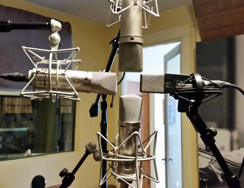
The shootout mic positioning (above)
MICS INCLUDED IN THE SHOOTOUT:
A) Vintage U87 pre-1988 which is a lovely sounding specimen ($3500 new)
B) Advanced Audio CM47fet which sells for $295 with mount & case
C) Advanced Audio CM87se which sells for $595 with mount & case
D) Vintage AKG 414eb P48 which is in lovely condition ($1000 new)
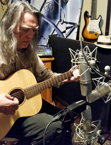
The microphone set-up was lowered and placed in front of our Tinker acoustic guitar.(above)
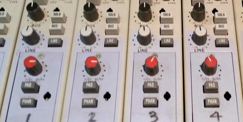
These microphones were patched directly into the Jensen transformer coupled preamps in the MCI/Sony MXP3036 console.Channel 1 is the AA CM47fet, Channel 2 is the Neumann U87, Channel 3 is the AA CM87 and Channel 4 is the AKG 414eb P48.The output gain of the CM47fet and the older U87 set to 200 ohms are nearly identical. A new U87Ai will have the same output level as the AKG414eb while the CM87se has 3db more output level than the original U87 but 3db less output than the AKG 414eb P48.

The outputs from the microphone preamplifiers appear in the patchbay of the MCI/Sony 3036 console and they were patched directly into the multi-track inputs 1-24 of the RADAR 24.

HERE ARE THE RAW, UNTREATED AUDIO CLIPS FROM THE SHOOTOUT


